The STORES adapter PCBs
You will find two red adapter PCBs in your kit. One flatcable adapter and one PCB adapter. Both of these adapters need to be assembled by soldering the correct headers to them. Combining these PCBs provides a clean and neat way to connect your ADALM2000 to a breadboard.
The flat cable adapter
Because normal flat cables do not fit in the ADALM2000, an adapter board is needed. You will need the following items from the kit to assemble this adapter PCB:
The assembly goes as follows:
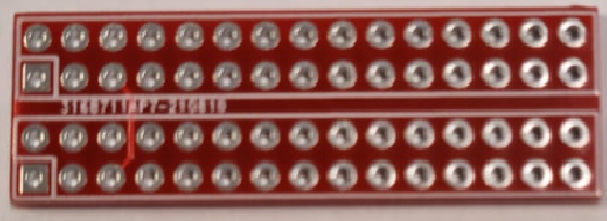
- Position the adapter PCB before you with the white lines on top and the squares on the left, like in the image.
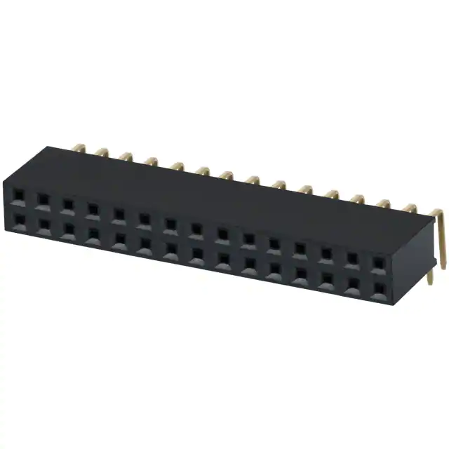
- Insert the right angle connector in the top row of holes, with the black plastic connector sticking out away from you.
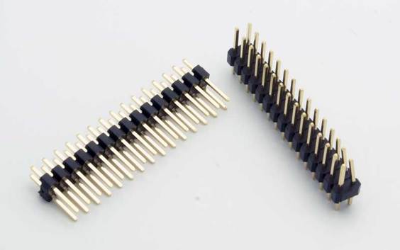
- Now insert the 15 by 2 pin header in the bottom rows of holes, with the long pins sticking out.
- Solder both connectors securely onto the PCB.
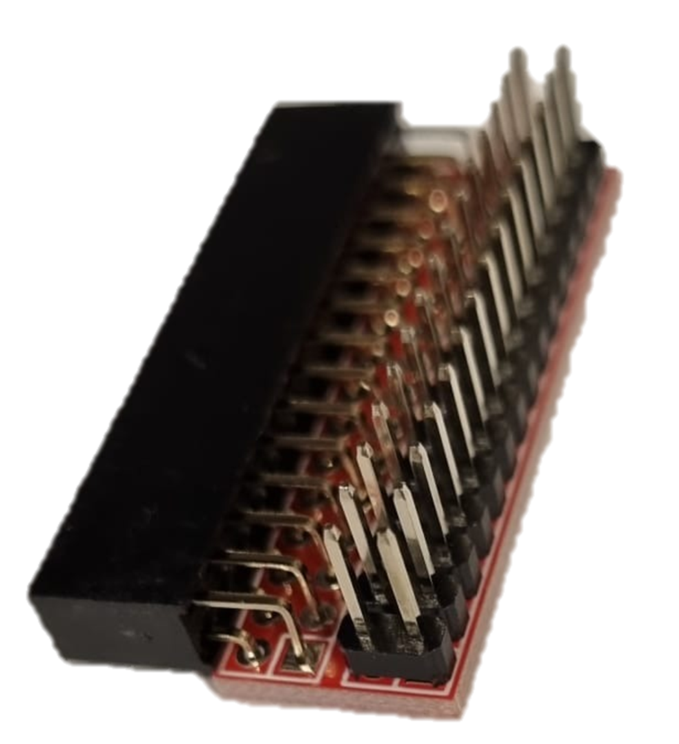
You now have a flat cable adapter PCB. The plastic connector plugs straight into the ADALM2000, and the flatcable connects to the pin header. The images below illustrate the intended assembly:
The breadboard adapter
Because normal flat cables so not fit in the ADALM2000, an adapter board is needed. You will need the following items from the kit to assemble this adapter PCB:
The assembly goes as follows:
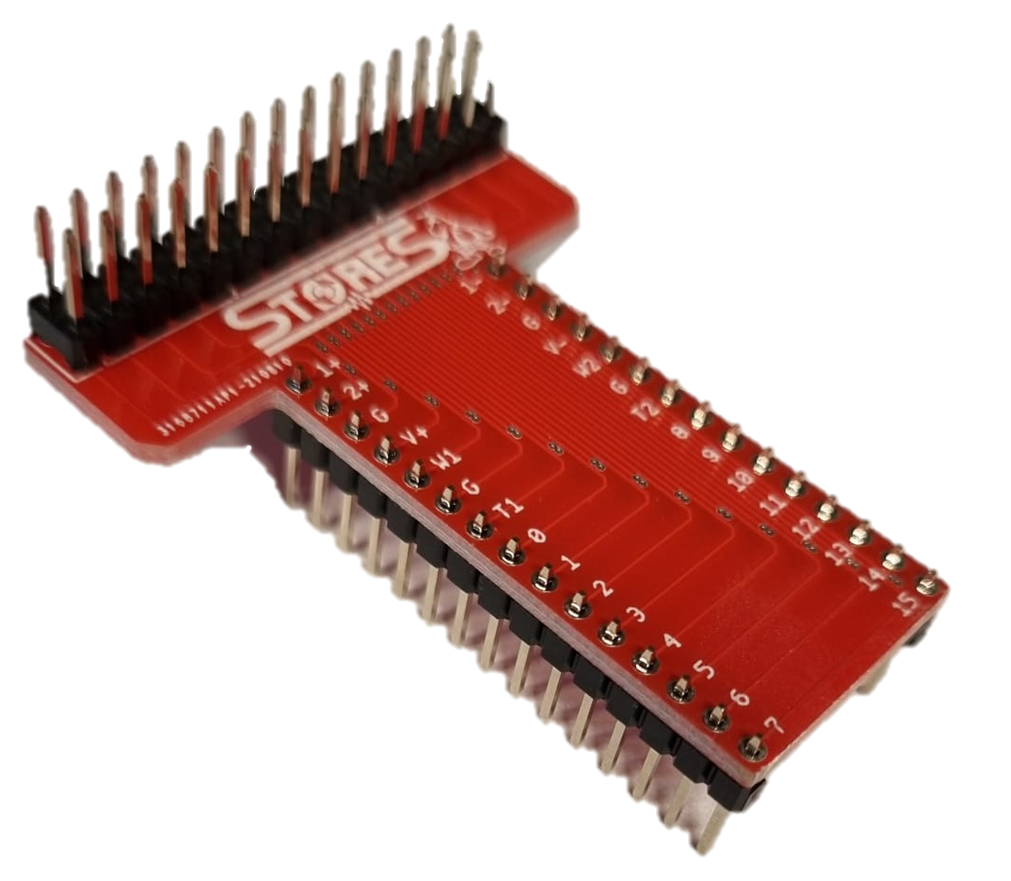
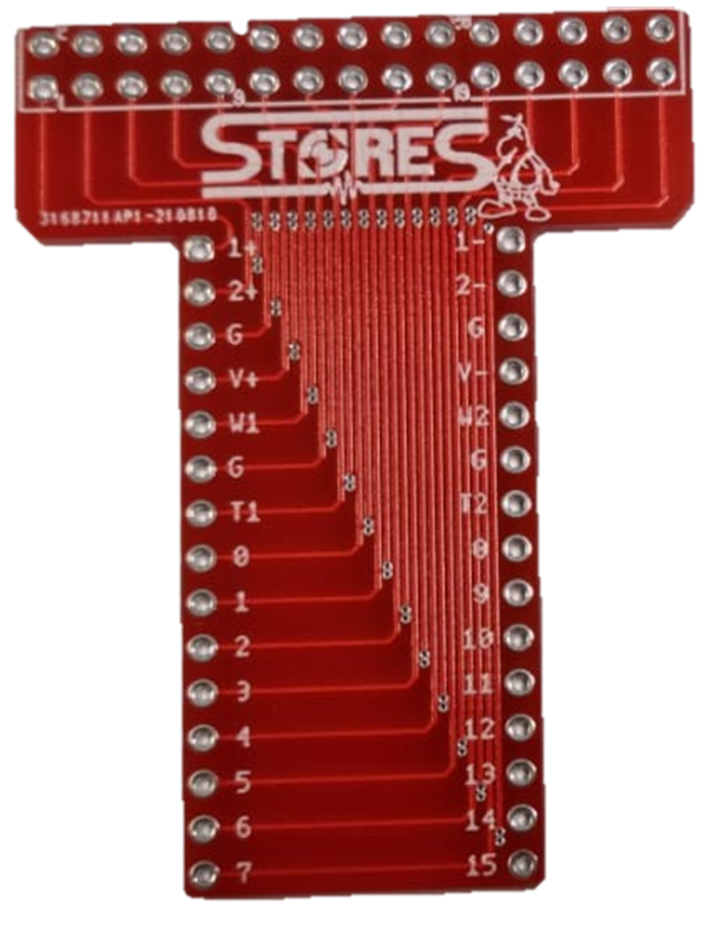
- Position the adapter PCB before you with the STORES logo on top, like in the image.
- Insert the 15 by 2 pin header in the top row of holes, long pins sticking out on top. Now solder these securely to the PCB.
- Now flip the board such that the STORES logo and the connector you just soldered are at on the bottom.
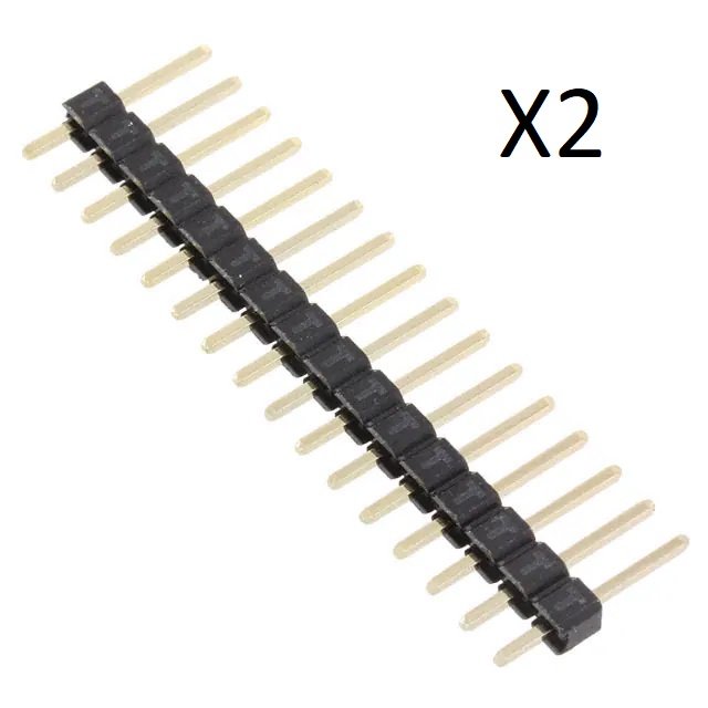
- Now insert the two 15 by 1 pin headers in vertical rows, with the long pins sticking out on top.
- Solder both connectors securely onto the PCB.
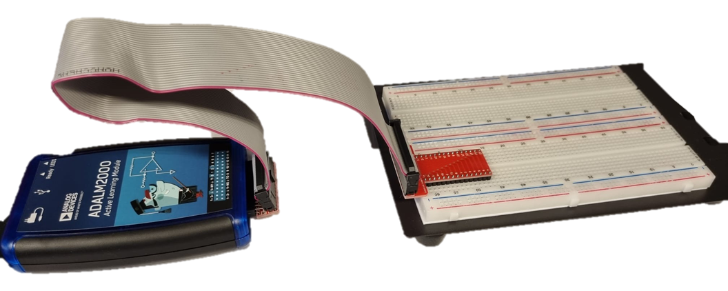
You now have a breadboard adapter PCB. The two vertical headers connect to your breadboard, with the breadboard lane separation in the middle. The 15 by 2 pin header connects to the flat cable. The images below illustrate the intended assembly, as well as the intended use of these boards to connect the ADALM to your breadboard.