Code Example
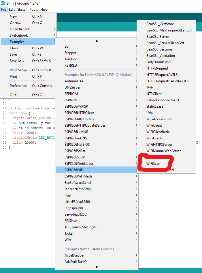
A great piece of code to test your IDE and NodeMCU is the WiFiScan sketch. It uses the WiFi.h library to scan for 2.4G WiFi networks in your area. To upload this code to the NodeMCU, connect the ESP to your computer, open the sketch in the Arduino IDE from the example menu (see the image below), and upload the code by clicking the arrow button in the IDE.
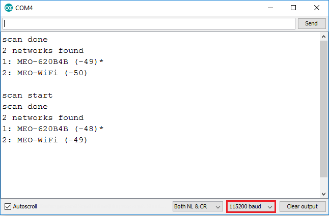
After uploading your code as described in the previous section, your microcontroller will send its output to the serial monitor. Open the serial monitor by clicking the button and have a look at your first running piece of code! It should look something like the image below. Please note the baudrate on the bottom right and set it to “115200” to match the uploaded sketch.
You may find that the default upload speed is quite slow. You can increase the upload speed under Tools -> Upload Speed to “3000000”, as this proves to be stable in our tests. Now try to upload the “Blink” sketch for the ESP8266 and see what it does!
When writing your own code, you can use the blue pin names as seen in the pinout image above for the digital and analog pins (A0, D0-D8). To use the other pins as GPIO, please use the GPIO number in the IDE. (i.e. to use GPIO7 as digital pin in your code use “7” as pin name)