Discretes & IC's
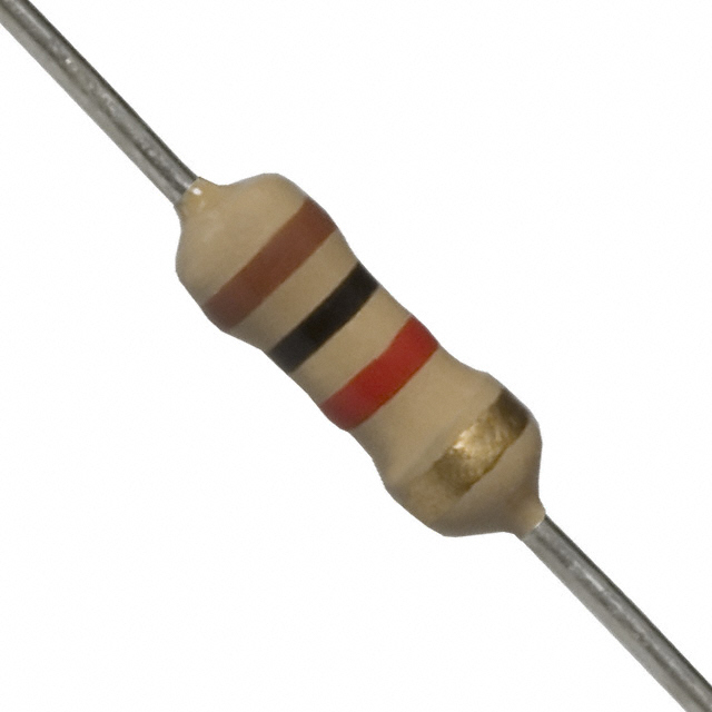
Resistors
Resistor values included in the kit
- 1R1
- 1R2
- 4R7
- 5R6
- 10R
- 16R
- 33R
- 47R
- 91R
- 100R
- 120R
- 150R
- 160R
- 200R
- 220R
- 270R
- 300R
- 330R
- 470R
- 560R
- 680R
- 750R
- 820R
- 1K
- 1.5K
- 1.6K
- 2K
- 2.2K
- 2.7K
- 3.3K
- 3.9K
- 4.7K
- 5.1K
- 6.2K
- 7.5K
- 9.1K
- 10K
- 11K
- 18K
- 22K
- 47K
- 51K
- 82K
- 100K
- 220K
- 470K
- 1.2M
- 2.7M
- 3.6M
- 4.3M
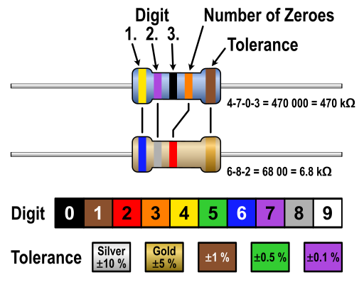
Resistors are components that limit current based on the resistance R and voltage V. The relation between resistance, voltage and current is set in Ohm's law, R=U/I. Resistors contain a colour code to depict their resistance value. A datasheet and insightful graphic are provided below. Below you will also find a figure that helps you determine the resistance of resistors with a 3 or 4 band code.
Resistor Graphic Colour codes Datasheet

Potentiometers
Potentiometers or potmeters or pots are variable resistors that vary their resistance by turning a knob. A classic potentiometer has three pins, two of them connected to the two ends of a resistive trace, and a wiper pin that rides on that resistive trace. By turning the knob, the wiper changes position on the resistive trace, which changes the resistance between the wiper pins and the outer pins.
A visual is provided which explains the abovementioned story for a 60Kohm potentiometer connected to 5V.
A potentiometer can be used as a 2 pin variable resistor by ignoring one of the outer pins or shorting the wiper pin with one of the outer pins. In this case it may be wise to put a resistor in series, as this setup may produce a short when turning the knob such that the resistance becomes very low.
Datasheet Wiper visual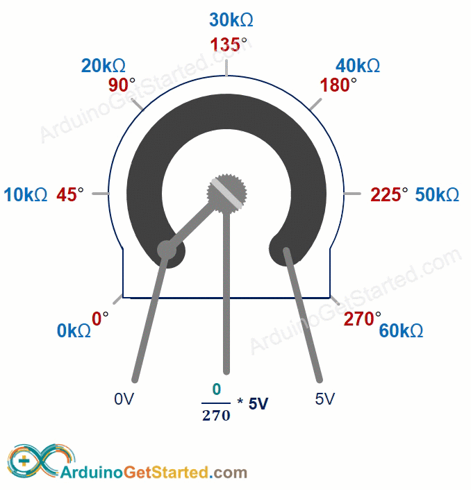

Ceramic Capacitors
Ceramic capacitors included in the kit
- 15p
- 20p
- 30p
- 47p
- 100p
- 220p
- 470p
- 1.0n
- 2.2n
- 3.3n
- 4.7n
- 6.8n
- 8.2n
- 10n
- 22n
- 33n
- 47n
- 68n
- 82n
- 100n
- 220n
- 330n
- 470n
- 860n
- 1u
A capacitor is a passive electrical component that is able to store energy in an electric field, similar to a battery but they are able to release the charge (Q) much faster. The amount of energy it is able to store is measured in Farads (F). Grossly simplified: it blocks DC and is able to pass AC, making it a common component in filters. A ceramic capacitor is built from one or multiple layers of metal, separated by a dielectric, in this case ceramic. Ceramic capacitors are non-polarized and traditionally lower in capacity than electrolytic capacitors.
Datasheet Capacitor visual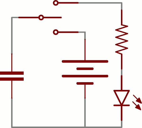
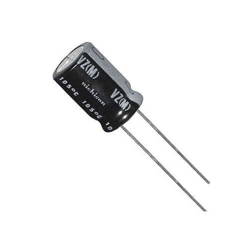
Electrolytic Capacitors
Electrolytic capacitors included in the kit
- 1uF
- 10uF
- 22uF
- 47uF
- 100uF
- 470uF
A capacitor is a passive electrical component that is able to store energy in an electric field, similar to a battery but they are able to release the charge (Q) much faster. The amount of energy it is able to store is measured in Farads (F). Grossly simplified: it blocks DC and is able to pass AC, making it a common component in filters. An electrolytic capacitor is built from one or multiple layers of rolled up metal, separated by a dielectric. Electrolytic capacitors are polarized and have a stripe on the side of the negative lead.
Datasheet Capacitor visual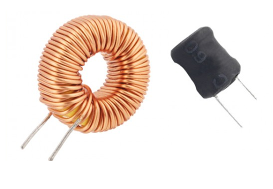
Inductors
Inductors included in the kit
- 100uH
- 470uH
- 10mH
- 22mH
- 47mH
- 100mH
An inductor is a passive electrical component that is able to store energy in a magnetic field. The amount of energy it is able to store is measured in Inductance (L). Grossly simplified: it resists changes in current and acts as a short when the electric field is maximized. An inductor is built from one or multiple turns of copper wire, most often wound around a metal core. Inductors are non-polarized.
Inductor visual LC visual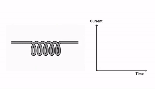
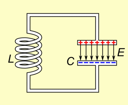
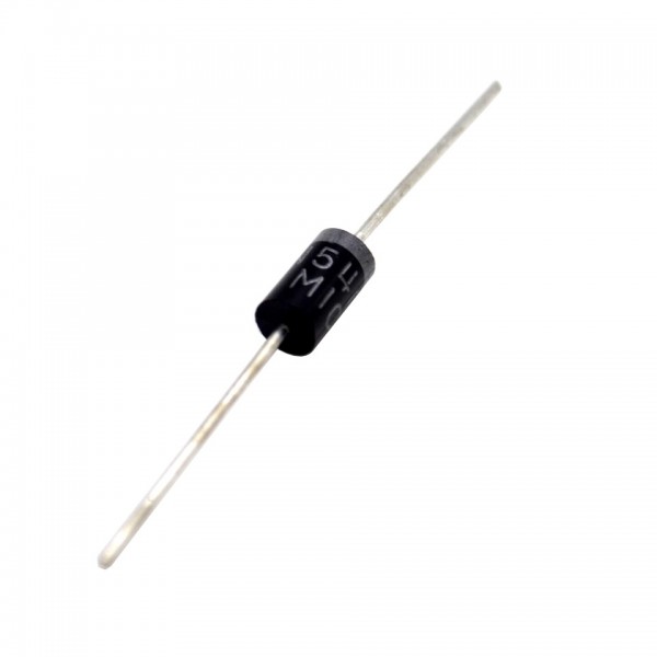
Diodes
Diodes included in the kit
- SB240
- 1N4148
- 1n4001
Diodes are passive devices that allow current to flow one way, but not the other. The current flows from anode to cathode, where the cathode is indicated by a stripe on the component. Diodes produce a voltage drop of around 0.6V and a given maximum current. The IV curves, forward voltage and maximum current are all stated in the datasheet.
SB240 Datasheet 1N4148 Datasheet 1N4001 Datasheet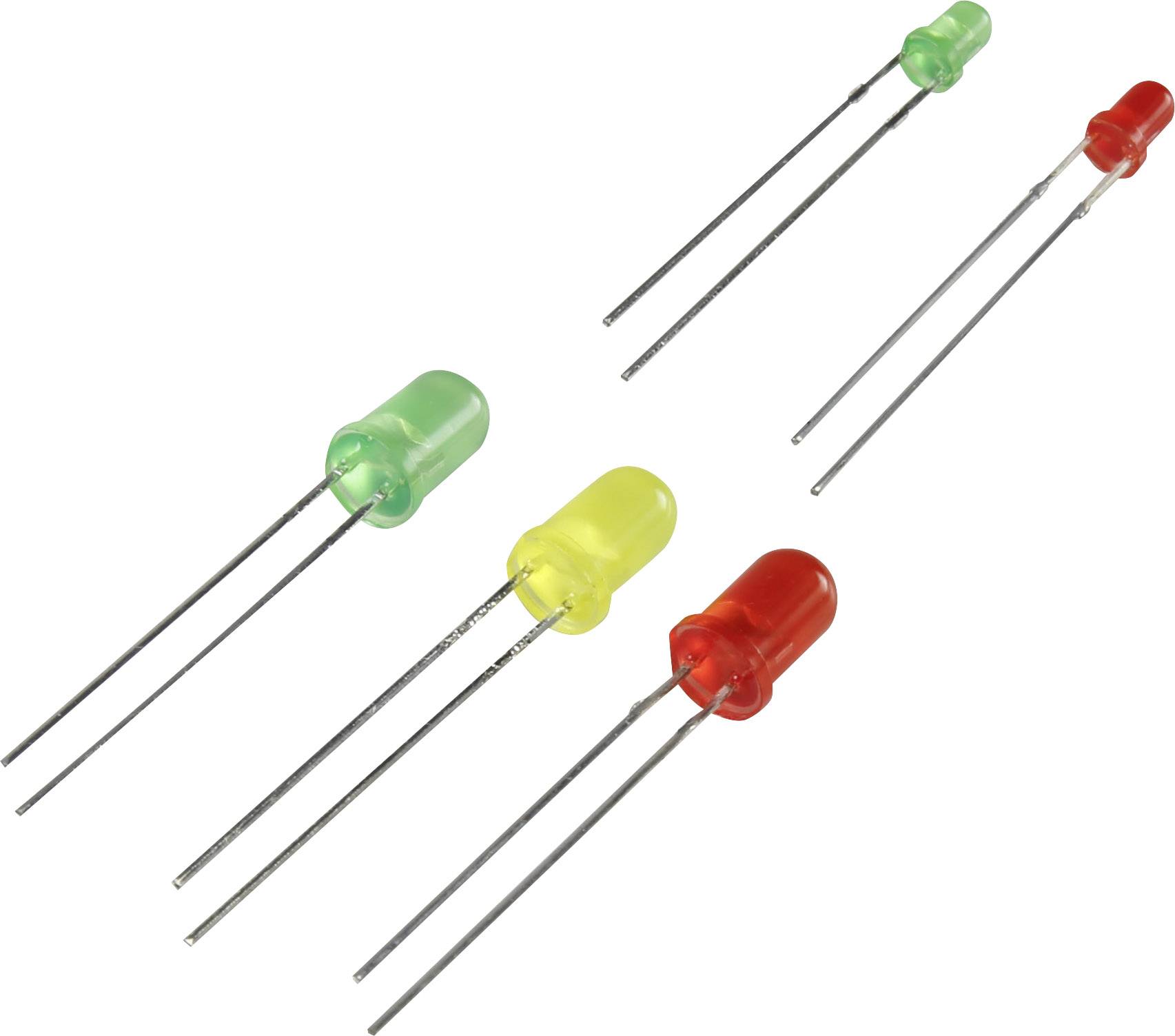
LED's
LEDs are diodes that emit light when current passes through them. They work like diodes, with similair IV curves and general behaviour. LEDs do however feature a higher forward voltage, which varies with LED type and colour. The LEDs in this kit come in 2 sizes: 5mm and 3mm. A safe maximum current for these LEDs is 15mA and the forward voltage can be measures with a multimeter. A resistor is needed to limit the current through the LED like shown in the example schematic provided below.
Example Schematic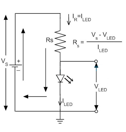
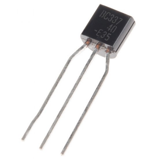
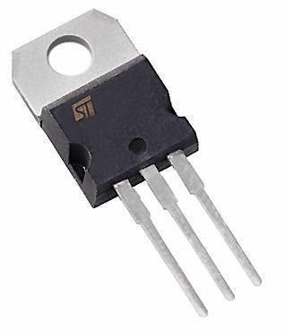
Transistor NPN
NPN Transistors included in the kit
- BC550
- BD139
- BF199
- 2N3904
- TIP3055
A NPN transistor is a passive current amplifying component. The exact workings of a transistor is outside the scope of this quick start guide, but the crude explanation is as follows. When a small current flows from the base to the emitter, a larger current (some scalar times the smaller current) flows from collector to emitter. The transistor is in essence two diodes back to back, meaning that for example there is a small voltage drop (approx 0.6V) between the base and emitter. The amplification factor and all the relevant graphs and data to design a current amplifier are included in the datasheet.
Current Flow BC550 Datasheet BD139 Datasheet BF199 Datasheet 2N3904 Datasheet TIP3055 Datasheet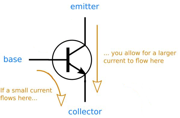
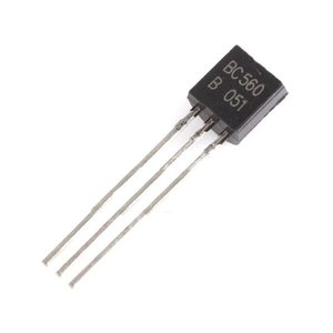
Transistor PNP
PNP Transistors included in the kit
- BC560
- BD140
- TIP2955
A PNP transistor is a passive current amplifying component. The exact workings of a transistor is outside the scope of this quick start guide, but the crude explanation is as follows. When a small current flows from the collector to the base, a larger current (some scalar times the smaller current) flows from collector to emitter. The transistor is in essence two diodes back to back, meaning that for example there is a small voltage drop (approx 0.6V) between the base and collector. The amplification factor and all the relevant graphs and data to design a current amplifier are included in the datasheet.
Current Flow BC560 Datasheet BD140 Datasheet TIP2955 Datasheet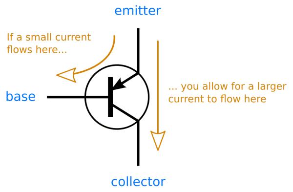
MOSFET N-channel
N-channel MOSFETs included in this kit
- STP16NF06L
- BS170
- IRF530
A N-channel MOSFET, or Metal-Oxide-Silicon Field-Effect Transistor, is a passive device that can regulate the electric conduction between its drain and the source pin by varying the voltage between the gate and the source pin. The exact working of a MOSFET is outside the scope of this guide, but the crudely simple explanation is that a MOSFET can be used as an electronic switch by applying the right voltage to the gate. In the case of a N-MOS, this "Gate-Source voltage" is a positive voltage. Always check the datasheet for details to properly design a system around a MOSFET!
STP16NF06L Datasheet BS170 Datasheet IRF530 Datasheet MOSFET P-channel
P-channel MOSFETs included in this kit
- ZVP2106A
- IRF550
A P-channel MOSFET, or Metal-Oxide-Silicon Field-Effect Transistor, is a passive device that can regulate the electric conduction between the drain and the source pin by varying the voltage between the gate and the source pin. The exact working of a MOSFET is outside the scope of this guide, but the crudely simple explanation is that a MOSFET can be used as an electronic switch by applying the right voltage to the gate. In the case of a P-MOS, this "Gate-Source voltage" is a negative voltage. Always check the datasheet for details to properly design a system around a MOSFET!
ZVP2106A Datasheet IRF550 Datasheet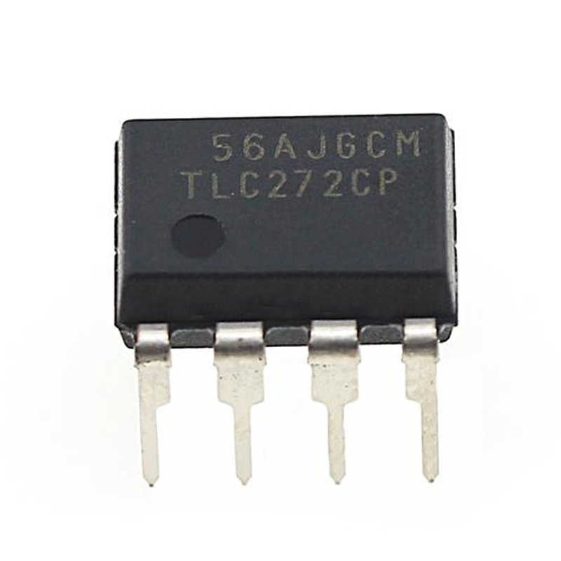
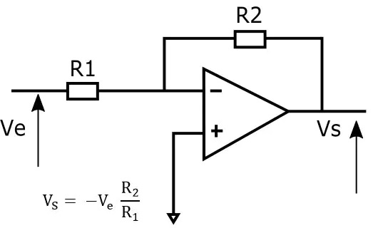
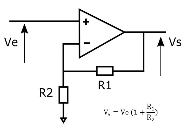
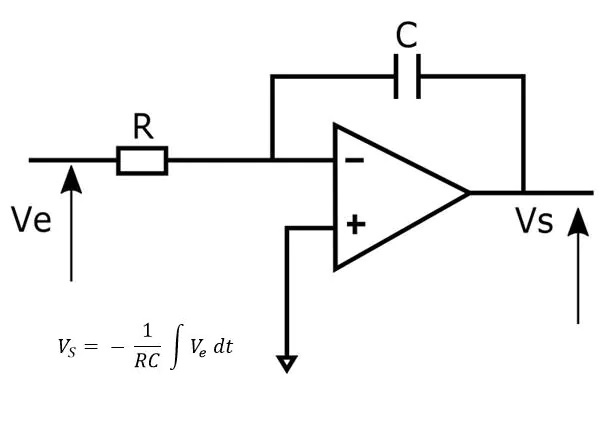
272 Opamp
This kit contains the classic 272 opamp. An operational amplifier is an active device that can amplify electrical signals. It is meant to be used with a feedback system containing for example resistors, capacitors or inductors. Different feedback systems can be used to achieve different behaviour. Most often you will find feedback systems to achieve a buffer, (inverted) amplification and active filters.
Example schematics for different applications are found below, as well as the datasheet for the included opamp.
Buffer Example Inverting Amplifier Example Non-Inverting Amplifier Example Integrating Amplifier Example TLC272 Datasheet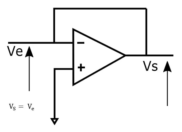
INA129 Instrumentation Amplifier
This kit contains the INA129 chip. Instrumentation amplifiers (INA) are active components that can amplify electrical signals. Unlike the opamp, it does not need a feedback circuit, as it has one on the chip. INAs are well known for their differential gain and common-mode-rejection capabilities. This allows them to amplify very small signals while rejecting any common-mode signals. Please see the datasheet for typical applications and other nessecary details.
INA129 Datasheet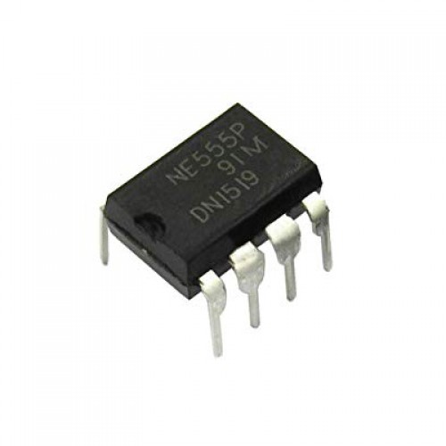
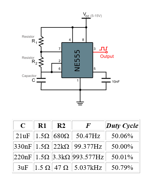
555 Timer
A 555 timer is an IC that can provide an adjustable square wave. The classic "555" name originates in the internals of the chip, where three internal 5 kΩ resistors are used to determine the characteristics of the output square wave. 555 timers are traditionally used with two resistors and two capacitors to create an astable oscillator circuit.
NE555 Datasheet Chip Pinout Example Schematic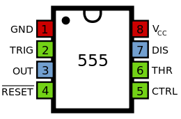
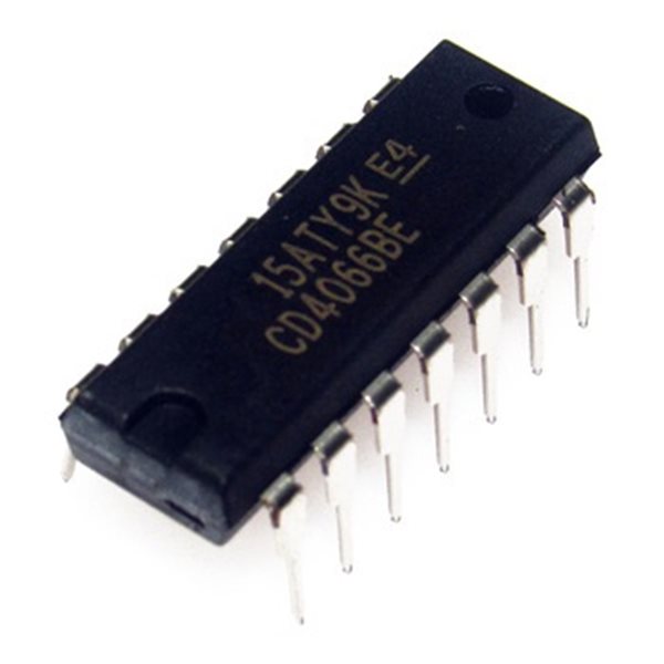
CD4066BE Quad Bilateral Switch
A CMOS switch is a digital IC that can be used to switch low level, low power signals. This chip contains 4 CMOS switches that can be controlled with logic signals at the control pins.
CD4066BE Datasheet Chip Pinout Example Schematic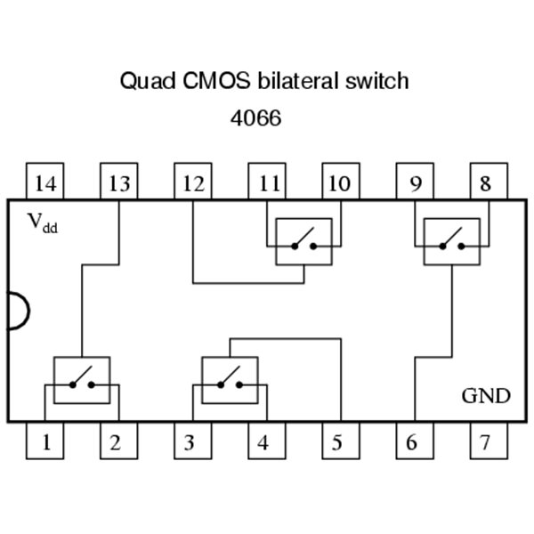
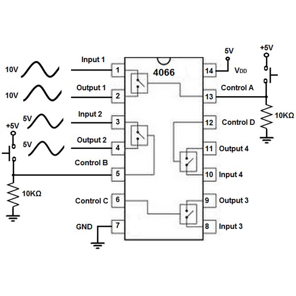
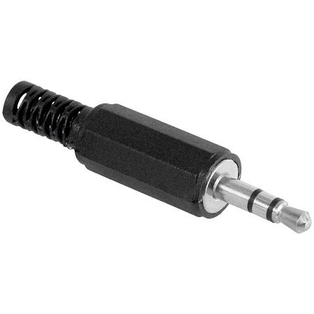
Jack Plug
This jack plug can be used to connect any device with a headphone output to your circuits. Please make sure to always DC decouple the jack terminals from your system with a capacitor to avoid magic smoke escaping from your expensive devices.
Pinout and Soldering Layout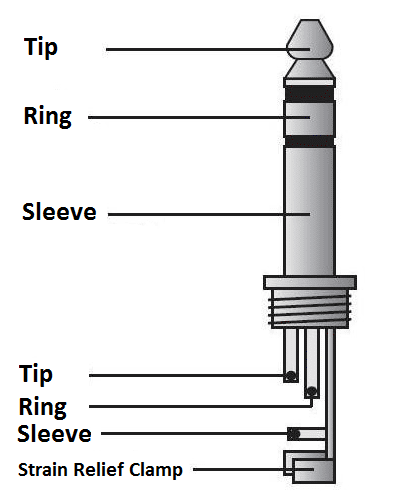
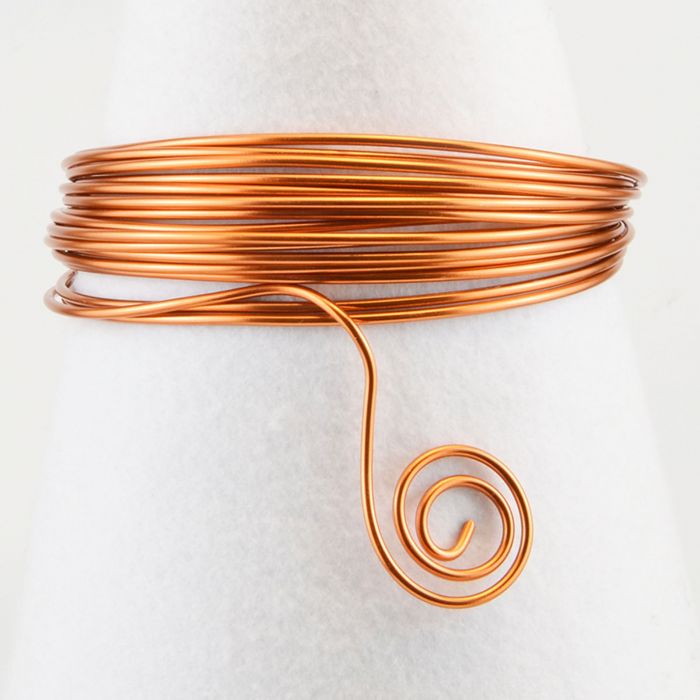
Copper Wire
This lacquered 1mm thick copper wire can be used to create your own low-inductance inductors. You can wind a fine air-core inductor by winding the wire around a nice pen. Unrelated fact; a Scintilla pen is 10.4mm, or 104e-4 meters in diameter near the clip. The button below provides an example on how to calculate the inductance of an air-core inductor is provided.
Inductance Calculation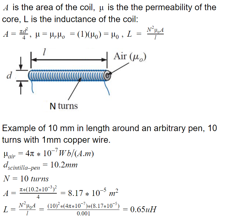